ACRYLIC FABRICATION / PROCESS SELECTION
One drawing. Two possible routes. Judge the finished part.
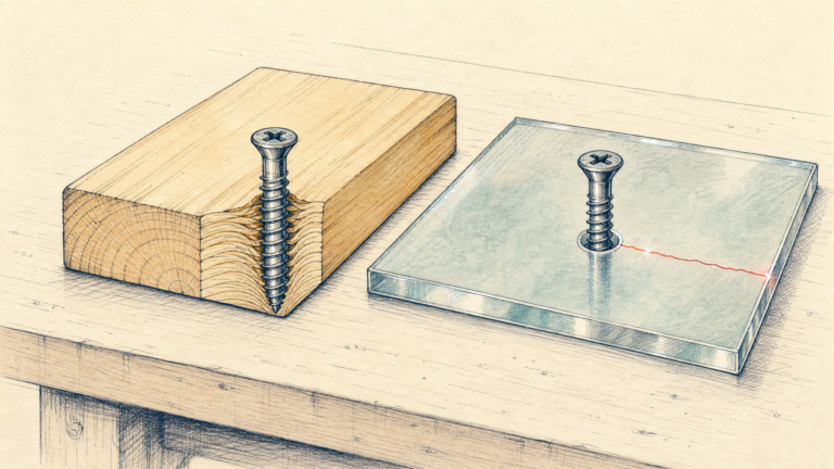
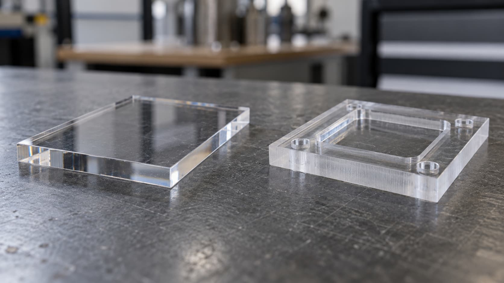
A laser can cut a flat acrylic outline and leave an attractive edge. A CNC router can cut the same outline while also milling a pocket, chamfer or controlled-depth recess. That makes the first question straightforward: does your part need only a through-cut profile, or does it have features that must be machined into the sheet?
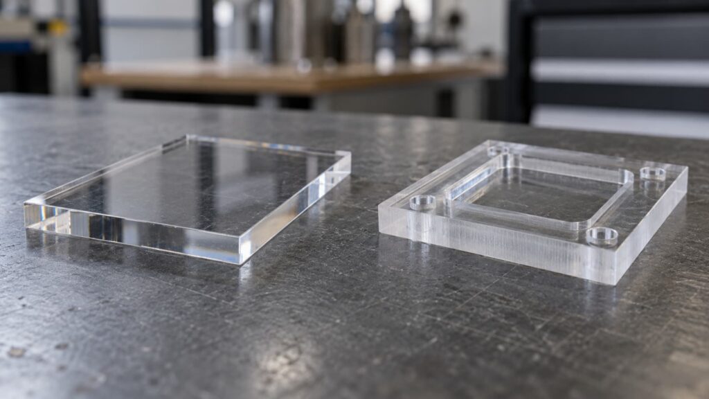
If both processes can make the geometry, the choice shifts to the finished part. An edge that looks clear in a photograph may still need a different finish for bonding. A precisely cut outline does not correct variation in the original sheet thickness. And the faster cut is not always the less expensive part once polishing, rejected pieces and inspection are included. Choose the process for the finished part, not just the cut.
Here, “laser” means an industrial CO₂ laser used on acrylic sheet, and “CNC” means routing or milling with a rotating tool. Clear acrylic behaves differently under many desktop diode lasers; the comparison below is about the processes a buyer would specify for fabricated PMMA parts, not about which hobby machine to purchase. Epilog’s acrylic guide explains the difference in laser source.
Start with the features on your drawing
Laser cutting is a strong candidate for flat parts made by cutting all the way through a sheet: shaped panels, lettering, frames and detailed profiles. The beam removes material along a programmed path without pushing a bit against the part. It can form small contours that would be difficult for a router bit to enter, provided the selected sheet and machine can produce an acceptable test piece.
CNC routing uses a physical cutter. It can cut the outer profile too, but it becomes necessary when the drawing calls for a pocket, a stepped surface, a counterbore, a controlled-depth groove or a machined edge. Its bit has a diameter, so an internal corner has a tool radius unless the design provides relief or uses another operation. Tool access and how the part is held in place matter as much as the outline.
This is a starting point, not a thickness-based rule. A display can contain laser-cut outer panels and CNC-machined bases. The drawing should identify the process-sensitive features of each component before anyone quotes the whole assembly as one operation.
| Part requirement | Process to review first | What to confirm on a sample |
|---|---|---|
| Flat through-cut outline with exposed edges | CO₂ laser | Edge appearance on the specified sheet and both faces |
| Pockets, counterbores, chamfers or controlled-depth grooves | CNC routing | Feature depth, internal radii and finished surface |
| Tight-fitting slots or holes in an otherwise flat part | Either, sometimes both | Actual fit after cutting and any finishing |
| Large or thicker part | Compare machine capacity and part geometry | Edge squareness, holding method and required finish |
| Assembly with different flat and machined components | A process for each component | Fit and appearance of the assembled first article |
Edge quality: glossy is only one requirement
On suitable acrylic, a CO₂ laser can produce a smooth, glossy-looking cut edge as it works. The cut is thermal: material at the edge is heated and removed. Its appearance changes with the PMMA grade, color, thickness, focus, speed and machine setup. The PLEXIGLAS machining guide recommends testing the actual sheet and notes that cut edges on thicker sheets can become slightly oblique. A clear-looking face alone therefore does not establish that the entire edge is square.
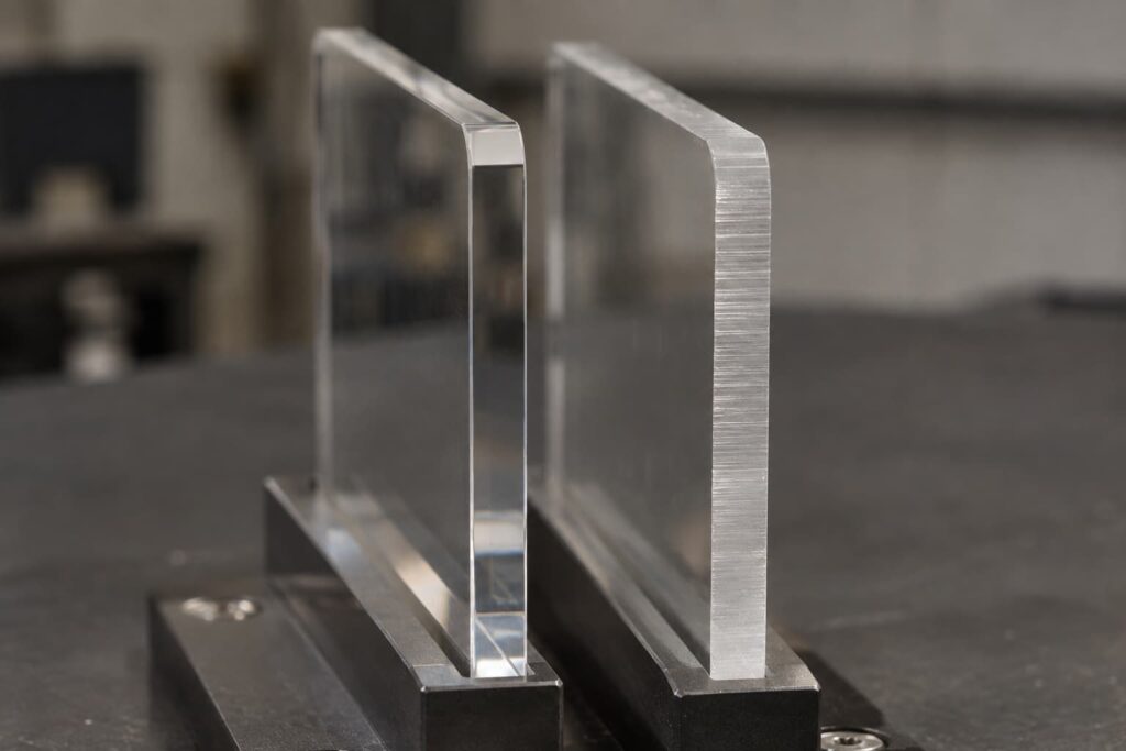
A router cuts mechanically. Depending on the cutter and settings, the fresh edge may show tool lines or appear matte. It can then be sanded or polished if the design calls for a clearer show edge. That added operation affects dimensions, handling and cost. Equally, a routed edge hidden inside an assembly may need only a controlled, clean cut; polishing every edge would add work without improving the finished product.
Define show edges (visible in use), fit edges (touching another component) and bonding edges separately on the drawing. A glossy edge may pass a display appearance check but still need preparation before a particular bonding method. Mechanical processing and localized heat can also introduce stresses that matter in later fabrication. The PLEXIGLAS machining guidance discusses machining stress and subsequent bonding; it does not imply that every cut part needs the same annealing step. Let the planned joint and the approved sample determine the finish sequence.
Do not assume cast or extruded acrylic will always give the better laser-cut edge. Suppliers describe differences in thickness consistency, engraving and edge behavior, but the result still depends on the particular sheet and laser setup. For a closer material comparison, see our cast vs extruded acrylic sheets guide and laser cutting material guide.
What changes as acrylic gets thicker?
More thickness means the cut must work through more material. For a laser, maintaining the desired appearance and edge geometry becomes more demanding; focus, power and feed have to suit the sheet. The PLEXIGLAS guide describes how beam focus and sheet thickness affect the angle and shape of a cut edge. For CNC, thicker material changes tool engagement, chip removal, fixturing and the time required to reach full depth.
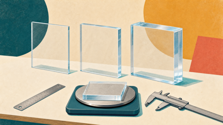
There is no useful universal statement that “laser works below X mm; CNC starts above X mm.” A machine might cut a thickness but fail the edge or fit requirement of your part. Conversely, a suitable machine and material may make a thicker laser-cut part acceptable for a less critical edge. Check machine capacity, specified sheet, geometry and acceptance standard together. If the sheet will slide into a precisely sized channel, the starting sheet-thickness variation may be more important than the way its outline was cut.
Which tolerance is actually critical?
“We need ±0.1 mm” leaves out the most useful detail: what dimension is being measured? An outside profile, a hole center, a slot width and the sheet thickness are different characteristics. A cutting machine may position a contour accurately while the incoming sheet varies in thickness. A laser-cut edge can also differ between the top and bottom surfaces; a nominal outline dimension cannot, on its own, describe edge squareness.
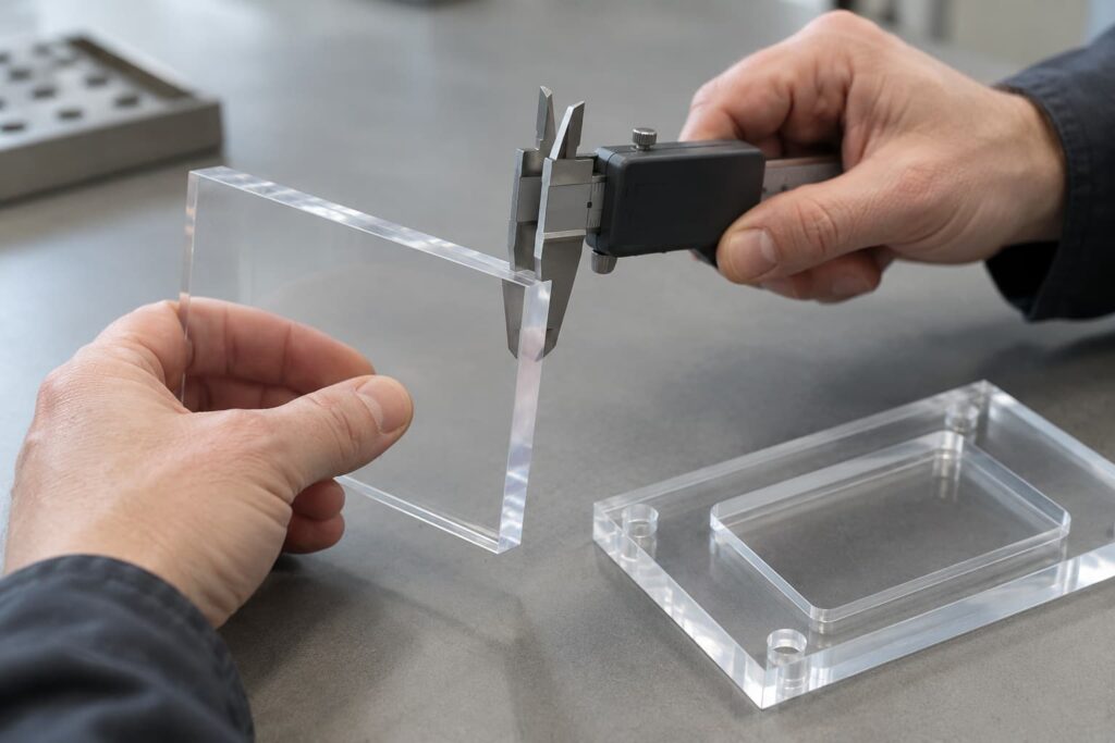
Mark the dimensions that make the part function. For a cover fastened to a machine, that could be hole positions relative to a datum edge. For an interlocking display, it could be the slot width relative to the measured sheet thickness of the mating tab, plus the desired assembly clearance. When a fit matters, specify where the dimension is checked and whether it is checked before or after polishing. A universal process tolerance copied from a supplier table cannot replace those drawing notes.
An approved first article should answer two separate questions: Does this part meet the drawing at the agreed measurement points? and Does it fit the mating part after all planned finishing? This is why a loose offcut with a good-looking edge cannot validate a production assembly.
Compare the cost of the finished part
A quote for cutting time alone is a poor comparison. Use the same drawing, specified acrylic, quantity and acceptance criteria for each viable route, then compare the work required to deliver an acceptable part:
For example, a hypothetical flat panel with a visible perimeter might leave the laser ready for inspection, while its routed version needs an added polishing operation. Change that drawing to include a recessed fixing point and CNC may be able to make the profile and recess in one setup, whereas a laser-only quote no longer describes the completed part. Neither example establishes a universal cheaper method; the geometry and approved finish changed the scope of work.
Quantity matters, but it does not decide the process by itself. Repeated parts may justify fixturing or a stable nesting plan. Small, detailed parts may create different handling and reject costs. Ask for a quote that identifies any secondary process instead of assuming that a low per-cut price covers a finished component.
Approve a representative part before production
Use a test piece made from the intended material and thickness, with the critical features from the drawing. Review it under the lighting in which the edge will actually be seen. Check both faces and the edge, measure functional features at the agreed points, and test a fit or bond when the final assembly depends on one. Record whether the edge shown is as cut or after polishing.
For repeat orders, keep the approved drawing revision, material identification, finish requirement and first-article photos together. That provides a practical reference if later pieces look different even though they were produced by the same named process. A material sample without the actual cut and subsequent operations will not reveal those differences.
What to send for an acrylic cutting review
Send the drawing or DXF/CAD file, acrylic type if known, nominal sheet thickness, quantity and the destination for delivery. Highlight show edges, bonding edges, critical holes or slots, any required recesses, and which dimensions control assembly. If you have a mating component, include its dimensions or a photo with a measurement reference. You can propose laser or CNC, but describe the finished-part requirement even if the method is undecided.
Grandview Acrylic offers both CO₂ laser cutting and CNC machining for custom parts. Share the part drawing, edge requirement and quantity so the fabrication route and any needed sample approval can be reviewed against the actual geometry.
FAQ
Is laser or CNC better for 5 mm clear acrylic?
For a flat through-cut with a visible edge, start by testing a CO₂ laser on the specified sheet. For a pocket, controlled depth or a fit that depends on a square edge, review CNC. At 5 mm, the part features and acceptance criteria give a better answer than the nominal thickness alone.
Does a laser-cut edge always need no polishing?
No. A suitable laser and material can produce an edge acceptable as cut, but visible striations, dull areas, edge angle or the planned bonding method may change the finishing requirement. Approve the edge on the actual part.
Can a CNC-cut acrylic edge become clear?
Yes, an appropriate finishing sequence can improve the appearance of a routed edge. Specify which edges need it and inspect the finished size if polishing affects a critical fit.
Conclusion
Choose laser first for a feasible flat through-cut when the approved edge meets the visual requirement. Choose CNC when the part needs machined depth or features the laser cannot make. Where both routes are possible, compare an actual sample, the functional drawing dimensions and the cost of delivering the finished, inspected part. That gives your supplier a real decision to price and gives you a part you can approve.
References / Further Reading
- PLEXIGLAS® Guidelines for Workshop Practice: Machining, especially sections 1.2 and 2.8.
- Trotec: Laser processing on acrylic.
- Epilog: Acrylic laser cutting and engraving.