PMMA processing / Forming & troubleshooting
A good formed part is defined after cooling.
Thermoforming acrylic sheets means heating PMMA until it can be shaped, forming it, and holding the geometry as it cools. Reaching the mold is only part of the job: a clear sheet can become a part with thin walls, tool marks, haze, or warpage.
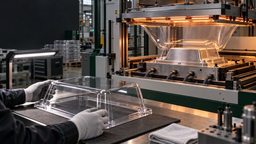
A repeatable result needs a controlled process window—the combination of material condition, sheet temperature, forming action, and cooling that produces an acceptable part. The grade must suit the process, heat must reach the sheet uniformly, and the cooled component must meet its geometry, surface, fit, and minimum-wall requirements.
A defect is not just a reject; it is evidence of where the forming window broke.
This guide connects forming methods, product-specific temperatures, wall distribution, and common defects. It also explains why a flat material sample cannot approve a three-dimensional part.
Four controls behind a repeatable acrylic form
- Material condition. Confirm the PMMA grade, cast or extruded route, color, surface, storage history, and masking instructions.
- Heat distribution. Control the sheet across its area and through its thickness—not only the heater or oven setting.
- Forming system. Match the tool, venting, vacuum or pressure, and material stretching to the required geometry and wall distribution.
- Cooled-part approval. Inspect dimensions, minimum wall, clarity, surface, fit, and downstream operations.
Thermoforming vs. vacuum forming: choose the route from the part
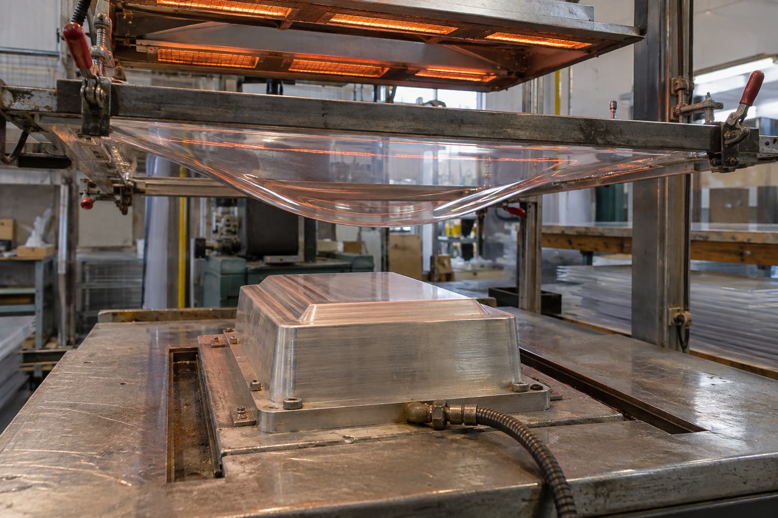
Thermoforming is the overall process. Vacuum forming is one method within it: air is evacuated between the hot sheet and the mold, allowing atmospheric pressure to push the sheet toward the tool. Pressure forming uses compressed air to provide additional forming force. The finished geometry should guide the method choice. [1]
Compare the geometry first. On smaller screens, swipe or focus the table and use the arrow keys.
| Route | Best suited to | Project question |
|---|---|---|
| Line bending | A straight fold along a narrow heated zone. | Is the design essentially flat panels connected by bends? |
| Drape forming | Broad, relatively gentle contours. | Can gravity and controlled contact reproduce the curve without a detailed vacuum draw? |
| Vacuum forming | Three-dimensional shells, covers, sign faces, and housings. | Can vacuum, venting, and tool geometry deliver the detail and wall distribution? |
| Pressure forming | Parts needing more forming force or sharper detail. | Does the detail or material behavior exceed what the available vacuum can reproduce? |
Line bending creates a fold; full-surface forming stretches material into a three-dimensional shape. For parts that need only straight bends, see how to bend acrylic sheets.
Before choosing a machine or quoting a tool, mark the overall geometry, draw depth, critical visible face, fit points, and expected quantity on the drawing. These determine whether bending, drape forming, vacuum forming, pressure forming, or a different construction method is appropriate.
Acrylic thermoforming temperature is a window, not one number
Published temperatures often refer to different products or measurement points. Cast and extruded acrylic behave differently, and a sheet temperature is not an oven setting. Manufacturer guidance illustrates the distinction:
- PLEXIGLAS: recommended material temperatures are 160–175°C for GS and 150–160°C for XT, with adjustment for forming degree, speed, and surface quality. [2]
- Lucite: sheet-temperature ranges are 290–320°F (about 143–160°C) for CP, 290–340°F (about 143–171°C) for CPX, and 290–350°F (about 143–177°C) for L cast sheet. [1]
These are product-specific reference ranges, not settings for every PMMA sheet and not Grandview product specifications. A purchase order that says only “acrylic” does not provide enough information for process planning.
Sheet temperature is not the heater setting
Acrylic transfers heat slowly through its thickness. Fast radiant heating can leave a hot surface above a cooler center. Forming too early can leave stress or poor detail; excessive or uneven heating can contribute to bubbles, surface damage, or tearing.
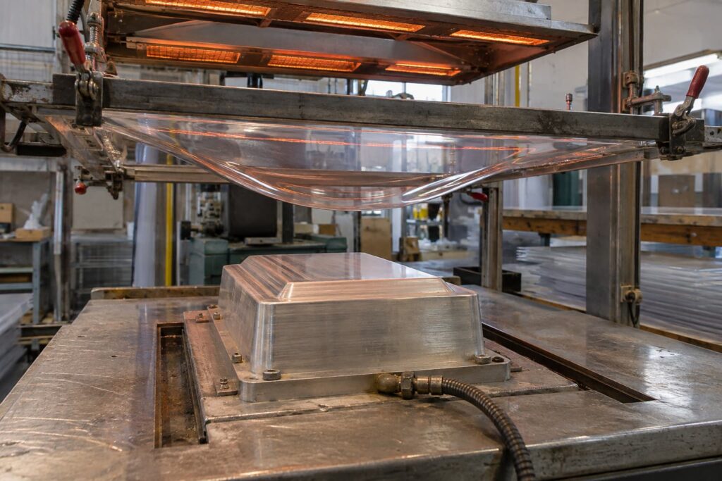
The Lucite guide describes an oven setting 20–40°F (about 11–22°C) above nominal sheet temperature for its products, with time adjusted to reach the forming state. This is a temperature difference, not another forming range. Do not copy that setting to a different oven, heater layout, grade, thickness, or color. [1]
The controlled variable is the condition of the sheet. Heater zones, heating time, suitable temperature measurements, sag behavior, and representative trials help reproduce it.
Grade, color, moisture, and masking change the trial
Neither cast nor extruded acrylic is automatically better for every part. Compare the exact grade against optical appearance, draw depth, tool contact, dimensional behavior, and availability. Pre-stretching—stretching the hot sheet before final tool contact—and plug assistance, where a shaped tool helps distribute material, also affect the result.
Color and surface treatments can change heat absorption. Moisture as well as overheating can be associated with bubbles, and predrying instructions vary by grade and storage condition. Masking must also be checked: some thermoformable films may remain, while paper or other films and adhesives may need removal. Follow the instructions for the actual sheet and masking system. [1] [2]
What vacuum forming changes in an acrylic sheet
The clamped sheet stretches rather than moving down as a uniform plate. Areas that travel farther or contact the mold later can become thinner, while other regions retain more of the starting gauge. Here, gauge means the starting sheet thickness.
Starting sheet gauge is not finished wall thickness
A 3 mm starting sheet does not mean every point of the formed part remains 3 mm. Draw depth, corner radius, mold orientation, pre-stretch, plug assistance, heating pattern, and contact sequence all change material distribution. [2]
When wall thickness affects rigidity, assembly, mounting, or light appearance, mark the critical measurement points and acceptable finished minimum wall. Evaluate the starting gauge against that geometry instead of selecting it in isolation.
Mold contact affects detail and appearance
The contact side can reproduce the mold surface. Texture, dust, scratches, vents, and local chilling can become visible in a clear part. Male and female molds also change the first contact point and the wall distribution. Mark the critical visible face before tool design, particularly for clear covers, illuminated components, and customer-facing housings. [1]
Venting lets trapped air escape from recesses so the sheet can reach the tool. Poor venting prevents complete contact, while visible vents can leave marks. Tooling therefore controls more than the initial shape: it influences surface quality, consistency, and rework.
Common acrylic thermoforming defects: causes and first checks

Different process problems can leave similar symptoms. Use this matrix to choose a first check, then review the material, equipment, tool, and cycle record together. The acceptance column identifies what to agree with the buyer; it does not establish a universal quality standard.
Read across: symptom → possible variables → first check → acceptance. Swipe horizontally to see all four columns.
| Symptom | Possible variables | First checks | Buyer acceptance point |
|---|---|---|---|
| Bubbles or blisters | Moisture, excessive temperature, local heater intensity, contamination. | Check grade and storage; compare defect positions with heater zones; review sheet temperature and supplier drying guidance. | Agree bubble limits on critical faces under defined lighting and viewing conditions. |
| Haze or stress whitening | Sheet too cool during stretching, excessive local strain, surface replication, residual stress. | Compare the deepest draw and tight radii with contact and non-contact faces; review temperature uniformity. | Approve clarity after forming and cooling, not from the flat sheet alone. |
| Poor detail or incomplete forming | Insufficient or uneven heat, vacuum leaks, missing or blocked vents, premature cooling. | Does the whole part lack depth, or does one recess fail? Inspect seals, vents, and the corresponding heater zone. | Required contours, mating surfaces, and details must be present and repeatable. |
| Thin walls or tearing | Deep draw, sharp transitions, uneven pre-stretch, hot spots, unsuitable starting gauge. | Map thickness at corners, sidewalls, and the deepest area; review radii, stretching, and contact sequence. | Measure minimum finished wall at drawing-defined points. |
| Webbing between features | Material gathering between nearby projections, geometry, excess local material, forming sequence. | Does it repeat between the same features? Review spacing, pre-stretch, and material distribution. | No folds that compromise appearance, trimming, fit, or function. |
| Tool, vent, or chill marks | Tool damage or texture, dust, visible vents, cold mold or clamp, early surface contact. | Inspect matching tool locations; compare consecutive cycles as the tool warms. | Define the critical face and approve a formed surface reference. |
| Warpage, cracking, or crazing after release | Uneven or rapid cooling, residual stress, early demolding, constrained shrinkage, drilling or bonding. | Record when it appears: on the tool, after release, after trimming, or after assembly. Review cooling and operation order. | Inspect the cooled, trimmed part using agreed dimensional references and fit conditions. |
Webbing is unwanted folded material between features. Crazing describes a network of fine cracks. Neither name identifies a single cause; location and timing are needed to narrow the investigation.
Use location, timing, and repeatability as evidence
Before changing several settings at once, ask these four questions:
- Every part or occasional? A repeating mark suggests a stable relationship with a heater zone, vent, clamp, or tool feature. Intermittent defects also warrant checks for contamination, material condition, handling, and cycle variation.
- Where? Match the location to the sheet, heater map, deepest draw, tool surface, and vents.
- When? Separate defects visible during forming from those emerging during cooling, demolding, trimming, drilling, bonding, or assembly.
- What changed? Review the lot, grade, masking, storage, heating, cycle timing, tool temperature, vacuum, and operator sequence.
For a useful defect review, collect whole-part and close-up photos, mark the defect location, and record the manufacturer, grade, starting thickness, first appearance, and whether it repeats in the same place.
Why a flat acrylic sample cannot approve a formed part
A flat sample can confirm incoming color, transparency, texture, and nominal gauge. It cannot show what stretching, tool contact, cooling, trimming, and assembly will do to the component.
Approve a representative formed sample for:
- Cooled dimensions and fit at defined datums—the reference surfaces or points used for measurement.
- Finished wall thickness at critical locations.
- Clarity, haze, color, surface marks, contours, and feature definition.
- Trimming, drilling, slots, or bonding in the intended production sequence.
- Appearance under the final lighting and viewing direction.
- Packaging that protects the shape and appearance-critical surfaces.
For printed or decorated acrylic, inspect artwork position and distortion after stretching. For a lighting cover, evaluate the formed part with its intended light source: wall distribution and tool contact may change the visible result.
From prototype to repeat production
An acceptable prototype becomes useful for production when its requirements are measurable. Retain an approved “golden” sample with the drawing revision and inspection points. Record the material and process conditions, and distinguish critical, major, and cosmetic characteristics.
Before production release, agree the assembly datums, minimum-wall locations, critical visible face, acceptable haze or marks, and edge condition. Identify operations after forming that might introduce stress, and how the part will be supported during packing.
Low-cost tooling is not automatically the lowest-cost option. Repeated wall, surface, or dimensional problems transfer cost into rejects, inspection, rework, and delayed assembly.
Application requirements change the approval standard
- Display covers and cosmetic housings: critical visible face, clarity, color, surface marks, and artwork position.
- Formed sign faces: contour definition, illuminated color, trimming, and mounting fit.
- Lighting covers and diffusers: wall and surface appearance under the intended light source.
- Machine guards and transparent enclosures: visibility, fit, mounting features, finished wall, and stress around drilled or machined areas.
- OEM housings: datums, mating points, trimming, hole positions, surface zones, and batch repeatability.
What to prepare before requesting a thermoforming review
Define the finished part rather than requesting only “vacuum-formed acrylic.” A useful review package includes:
- Drawing: CAD or dimensioned PDF, application, and any reference image.
- Material: manufacturer or grade, cast/extruded route, color, surface, and starting gauge.
- Finished requirements: dimensions, visible face, minimum wall, fit, and stiffness needs.
- Production: quantity, prototype needs, trimming, drilling, printing, bonding, or assembly.
- Release and delivery: inspection criteria, packaging, and delivery requirements.
If the grade is undecided, describe the appearance, geometry, end use, and next fabrication steps. Grandview Acrylic can review the sheet or blank requirement and the proposed fabrication route before quotation. For downstream operations, see acrylic machining and CNC processing.
Frequently asked questions
What temperature is used to thermoform acrylic sheets?
Use the material-temperature range for the exact product, then validate sheet condition and uniformity in a representative trial. Published values vary with grade, cast or extruded route, thickness, forming speed, heating method, and surface requirements. An oven setting is not a sheet temperature.
Is cast or extruded acrylic better for vacuum forming?
Neither is a universal winner. Some extruded grades use lower forming-temperature ranges, while a cast product may meet other optical, surface, thickness, or project needs. Evaluate the specific grade against geometry, forming force, visible face, finished wall, and sample acceptance.
Does acrylic need to be dried before vacuum forming?
Grade, storage history, moisture exposure, thickness, and heating method determine the need. Bubbles can also come from overheating or local heater intensity. Check the cause and follow the material supplier’s drying guidance rather than adding a generic cycle.
How should finished wall thickness be specified?
State the starting gauge, then mark critical measurement locations and their minimum acceptable finished wall on the drawing. Stretching changes local thickness, so a starting-sheet specification alone cannot approve the formed component.
Approve the cooled part, then lock the process
Successful acrylic thermoforming means repeatedly meeting the cooled part’s geometry, minimum wall, surface, optical, fit, and downstream-fabrication requirements. Start with the exact grade and finished specification, establish the forming window through representative trials, and read defects by their position, timing, and repeatability.
References and further reading
- Lucite Acrylic Sheet / Thermoforming. Lucite International technical bulletin, hosted by EMCO Plastics. Supports product-specific sheet temperatures, oven guidance, masking, tooling, and cooling. View source (PDF).
- Guidelines for Workshop Practice: Forming PLEXIGLAS. PLEXIGLAS / Röhm. Supports GS/XT material-temperature guidance, forming methods, stretching, and wall distribution. View source (PDF).
- Bending and forming PLEXIGLAS. PLEXIGLAS / Röhm. Further reading on heating, forming preparation, and trial pieces. View source.